Configure Inter VLAN Routing on Cisco Router and Layer 3 Switches
How to Configure Inter-VLAN Routing on Cisco Router and Layer 3 Switch?
A step by step guide to configure Inter-VLAN Routing on the Cisco router or layer 3 switches. Basically, on a VLAN, no host can communicate with hosts within other VLANs. It means only hosts that are members of the same VLAN can communicate with each other. So if you want your VLANs hosts can communicate with each other, you must configure inter-VLAN routing using a router or a layer 3 switch. Here we completely demonstrate the Inter-VLAN configuration using a Cisco router and a layer 3 switch.
The router you are using for Inter-VLAN routing must be compatible and support Inter-Switch Link (ISL) which is a Cisco Systems proprietary protocol, and IEEE 802.1q frame format for routing on the Fast Ethernet interfaces. In Inter-VLAN the physical Fast Ethernet interface of the router is divided into sub-Interfaces for each VLAN. You can set IP address for each sub-Interface in order to route between VLANs.
How to Create VLAN on Cisco Switches?
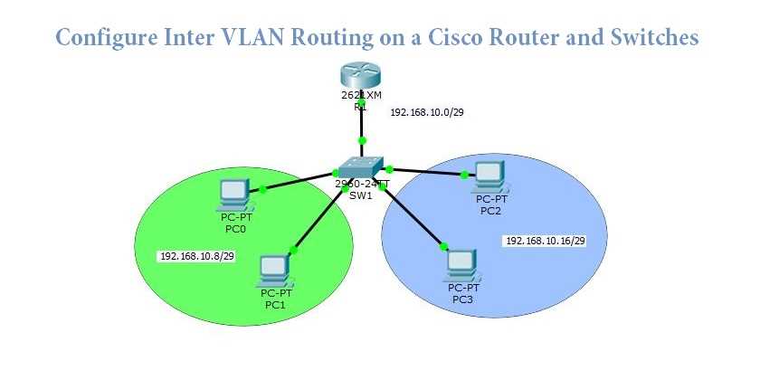
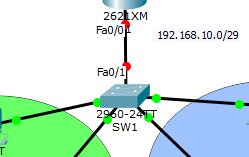
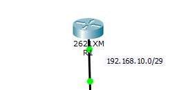
Let’s configure it on the below Inter-VLAN routing Lab. Download the Packet Tracer Inter-VLAN routing Lab for CCNA or create your own Lab.
1. First of all, create two VLAN in the switch and named VLAN A and VLAN B with the following command.
Switch>enable
Switch#configure terminal
Enter configuration commands, one per line. End with CNTL/Z.
Switch(config)#vlan 2
Switch(config-vlan)#name VLAN-A
Switch(config-vlan)#vlan 3
Switch(config-vlan)#name VLAN-B
Switch(config-vlan)#exit
2. OK, the VLANs A and B are created successfully. Now check them with “show vlan” command.
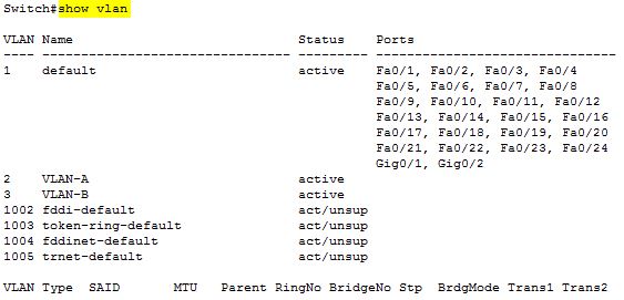
3. You see the result in the screenshot, the VLANs are ready for assigning switch ports to them.
Assigning Switch Ports for VLANs
In this section, the switch ports are divide and assign to VLANs. Before configuring Inter-VLAN routing, a host in a VLAN can only communicate within its own VLAN and not reach to other VLANs. So let’s configure it.
1. Try to assign switch ports for each VLANs with the following commands.
Switch(config)#interface fastEthernet 0/2
Switch(config-if)#switchport mode access
Switch(config-if)#switchport access vlan 2
Switch(config-if)#exit
Switch(config)#
Switch(config)#interface fastEthernet 0/5
Switch(config-if)#switchport mode access
Switch(config-if)#switchport access vlan 2
Switch(config-if)#exit
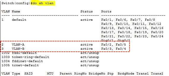
2. Now the port FastEthernet 0/2 and FastEthernet 0/5 are members of VLAN 2 which named VLAN-A. Go to set the PC3 and PC2 to VLAN-B.
3. Let’s assign a range of ports to a VLAN using “interface range” command.
Switch(config)#interface range fastEthernet 0/3-4
Switch(config-if-range)#switchport mode access
Switch(config-if-range)#switchport access vlan 3
Switch(config-if-range)#exit
Note: The interface range command can assign a range of interfaces to a VLAN. Read more about basic VLAN configuration on “Configure VLAN on Cisco Switches Using Cisco Packet Tracer” post.
4. Now we have just done the basic VLAN configuration like creating VLAN and assigning switch ports to VLANs. Let’s enable Trunking mode on the switch port to the router and then configure Inter-VLAN routing on the router.
Configure Trunking Ports on Switch
With the command “switch port mode trunk” you can configure trunking on the FastEthernet 0/1 port of the SW1. The VLAN Trunking Protocol (VTP) let the VLANs transmit theirs traffics over a physical line simultaneously. Read more about VTP on Wikipedia website.
1. Just navigate to FastEthernet 0/1 interface and type “switchport mode trunk“ the press enter to enable trunking on Fa0/1 interface line.
Switch(config)#interface fastEthernet 0/1
Switch(config-if)#switchport mode trunk
Switch(config-if)#
2. Now the VLANs can transmit traffic over the FastEthernet 0/1 without any problems.
Note: Try to enable trunking mode only to interface between to switch or router devices. It’s not necessary to enable it on the interface of the switch to PC.
Configure Inter-VLAN Routing on Cisco Router
Finally, the lab is ready to configure Inter-VLAN routing. If you test the PCs, they can ping with each other within a VLAN but not with other VLANs. So in order to communicate they need routing. Not network routing protocols such as Static routing or dynamic routing like RIP, and OSPF. Just need Inter-VLAN Routing which you simply configure according to below step by step Inter-VLAN routing guide.
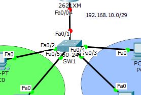
1. Try to assign an IP address to the router and enable the interface you want to configure inter-VLAN routing.
Router>enable
Router#configure terminal
Enter configuration commands, one per line. End with CNTL/Z.
Router(config)#interface fastEthernet 0/0
Router(config-if)#ip address 192.168.10.1 255.255.255.248
Router(config-if)#no shutdown
2. Good, the IP 192.168.10.1 with the subnet mask of 255.255.255.248 is assigned for physical FastEthernet 0/0 interface.
Note: We need to have subinterface for each VLANs on the router. The subinterface is a virtual interface card that inter-VLAN doing routing using them.
3. Now try to create a subinterface for each VLAN with interface command and assign IP address from the different network for each VLAN. In this case, I have subnetted the 192.168.10.0/24 IP address to 3 networks.
Router(config)#interface fastEthernet 0/0.2
Router(config-subif)#
Router(config-subif)#encapsulation dot1Q 2
Router(config-subif)#ip address 192.168.10.9 255.255.255.248
Router(config-subif)#
4. See the result with “do show ip interface brief” from sub-interface area.
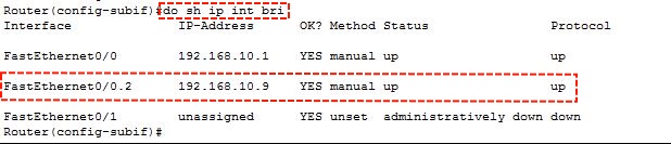
The virtual sub-interface FastEthernet0/0.2 has created and it has the 192.168.10.9 IP address. This sub-interface act as a default gateway for VLAN-A with an address of 192.168.10.8/29.
5. Do the same to create a sub-interface for VLAN-B also.
Router(config)#interface fastEthernet 0/0.3
Router(config-subif)#ip address 192.168.10.17 255.255.255.248

% Configuring IP routing on a LAN subinterface is only allowed if that
subinterface is already configured as part of an IEEE 802.10, IEEE 802.1Q,
or ISL vLAN.

Router(config-subif)#encapsulation dot1Q 3
Router(config-subif)#ip address 192.168.10.17 255.255.255.248
Router(config-subif)#
6. Everything is fine, but you see the error with red colour! It is because we forgot to set the encapsulation dot1Q command. Before assigning an IP address to a sub-interface, you should set IEEE 802.1q with encapsulation command.
Finally, all VLANs hosts can communicate with each other. That’s all you need to configure Inter-VLAN routing on your corporate network. Download the complete Lab of Inter-VLAN routing Cisco Packet Tracer Lab. Follow the below steps if you want to configure inter-VLAN on Layer 3 Switches or troubleshooting inter-VLAN on routers and switches.
Configure Inter-VLAN Using Layer 3 Switches
Work the same, just need a Cisco Layer 3 switch. To configure Inter-VLAN on a Layer 3 switch, you must assign an IP address to VLANs instead of sub-interfaces. Assigning an IP address to VLAN is easy, only read the “Assigning IP address to VLAN” section at the end of this articles.
To configure Inter-VLAN routing using layer 3 switches, you don’t need router anymore. All configuration has done within the layer 3 switch.
Troubleshooting and Assigning IP address to VLANs
As this post is related to configure Inter-VLAN routing, so we must do some more about VLAN configuration such as assigning IP address to VLANs, controlling VLANs remotely with Telnet, and some essential troubleshooting commands.
How to Assign an IP address to VLANs?
In order to assign an IP address to a VLAN, simply go to VLAN and set the IP address like assigning IP address to an interface of a router.
Switch(config)#interface vlan 1
Switch(config-if)#ip address 192.168.10.4 255.255.255.248
Switch(config-if)#no shutdown
Check it with “do show ip interface brief” command, whether the default VLAN 1 has gotten the IP address of 192.168.10.4/29 or not.

Yes, that’s fine. This can help you remotely configure VLANs through the internet or network.
Troubleshooting Inter-VLAN Routing
To see the VLANs on a switch, type the “show vlan” command. This command will list all created VLANs within a switch.
The “show interface trunk” command shows encapsulation and trunking status.
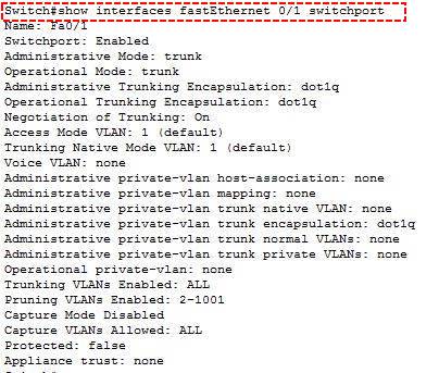
The “show interfaces fastEthernet 0/1 switchport” display the status of a specific switch port. See the result on the screenshot.
OK, I think it’s enough for Configuring Inter-VLAN routing. I hope you find this configure Inter-VLAN routing article’s helpful and if you have any problem or question regarding this article, ask us through the comment section.
Need to enable, routing in L3 switches “ip routing”.
Great!!
Dear, you explain think so good. I got it completely thanks for this effort.
This example is not complete
Your comment is not complete too. Please let me know which part is not complete?
Thanks
what are the IP addresses of the Pcs for each vlan?
Sorry for my englis.
Thanks
check my account for more info
Thank you
Of course they are complete. Thanks to the uploader, very clear explanation!
I hope you figured out already but if not just roll over the mouse over the PCs and they will pop up all details. For VLAN A PC0 is 192.168.10.10, PC1: 192.168.10.11. VLAN-B PC2: 192.168.10.18 and PC 3: 192.168.10.19
Its helps me to learned some Cisco device configuration.
Thanks by
Sourav
Still incomplete config.
Missed Switch(config)#ip routing
https://www.cisco.com/c/en/us/support/docs/lan-switching/inter-vlan-routing/41860-howto-L3-intervlanrouting.html#anc6
LOL, the correction I mentioned in my reply yesterday is now gone…..
This will not work on a L3 switch without the statement “ip routing”, which signals the switch to allow inter-vlan routing.
Very good! Thank you!
Thanks for making me to understand how to create VLANs, assigning port number, Assigning IP address to VLANs and also to configure trunk.
I had an assignment on how to design a network topology using three VLANs with three Switches. Each switch connected to three different VLANs such as VLAN 10, VLAN 20 and VLAN 30. Configure the Management IP for each interface of the VLAN include VLAN 1. Configure the VLANs so that the same VLANs should be able to communicate. Note: Determine your IP addresses to be used in your task.
Very well presented. Every quote was awesome, and thanks for sharing the content. Keep sharing and keep motivating others.